This is how I have done it in the past and will do it soon. I put this together as a quick reference for my install, but thought it might be useful to someone. It assumes the engine is already apart which is the easy part and is written for the stock piston and rings. I will modify it if I missed something or find an easier way:
1. Remove seat, tank, exhaust from front of cylinder head and at rear mount, smog line/bolt at front of cylinder, drain radiator and remove hose at front of cylinder, remove two lower subframe bolts, and loosen upper subframe bolt, loosen clamp holding carb at cylinder head, lift up subframe and separate carb with boot attached from cylinder head, remove cylinder head cover/bolts, wind up cam chain tentioner (CCT), remove cam holders/keepers/bolts, remove cam, remove cylinder head bolts and cylinder head, remove one lower cylinder bolt and cylinder, remove piston pin clip, piston pin, and piston. Whew, that was easy. Now the hard part.
2.Clean cylinder and piston using contact cleaner, and then hot soapy water.
3.Finish off inside of cylinder using ATF on a clean paper towel. Wipe until no more metal shows up on paper towel (leaves a trace of ATF on the cylinder hone marks).
4.Finish wipe using a clean paper towel until no more ATF residue shows up.
5.Wipe piston rings using a clean paper towel to remove excess oil.
6.Put piston pin clip in piston recess on CCT side first, before installing piston (limited access on this side, so do it before installing)(Piston pin clips shall be installed with open ends facing aft and horizontal.).
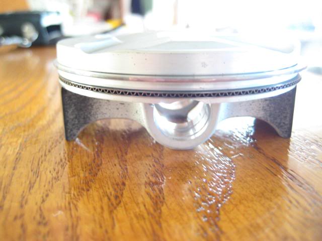
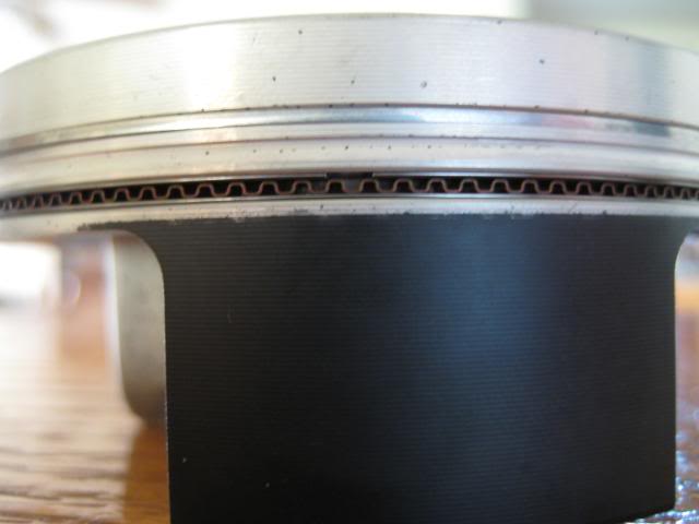
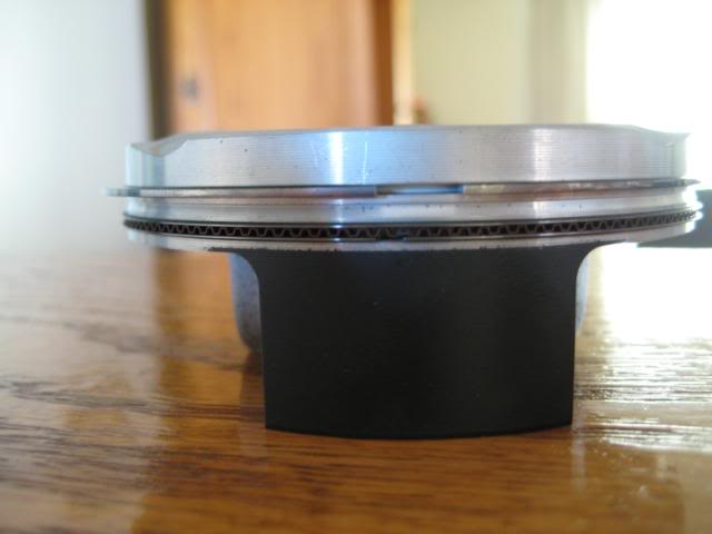
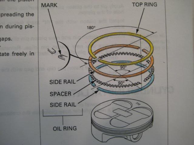
7.Install rings as shown:
a.Install wavy oil ring first in lower groove aligning cutout 90 degrees CW to the IN mark stamped on the piston. The oil ring must be installed first or it will hang up and not fully compress into the groove.
b.Install lower side rail below the oil ring (in the same groove) 180 degrees CW from the IN mark stamped on the piston which will be a further 90 degrees CW from the oil ring cutout.
c.Install the upper side rail above the oil ring (in the same groove) 270 degrees CW from the IN mark stamped on the piston which will be a further 90 degrees CW from the lower side rail cutout.
d.All three rings should be able to be compressed flush with the side of the piston with light finger pressure, if not, something is buggered up, probably the wavy oil ring.
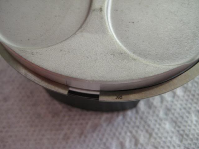
e.Install the top ring in the upper groove ensuring the mark (RK in my case) is facing up and is 180 degrees CW from the IN mark stamped on the piston.
f.It is not critical that all these ring gaps be precisionally placed (I use ± ¼ inch), but just make sure none of the lower 3 ring gaps are aligned with each other. If they are aligned, oil can leak through from one ring to the next which is not good.
8.Put one drop of oil on piston pin and rub all over shinny surface.
9.Put one small drop of oil on finger and swipe on each side of piston skirt (at piston pin holes), but very little oil.
10.Install lower dowel pins into case holes at the fwd right side and aft right side.
11.Ensure mating surface is clean and install lower cylinder gasket (no sealant required).
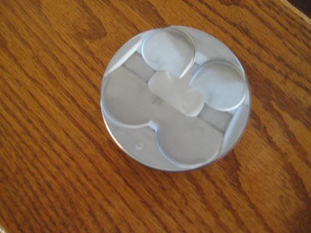
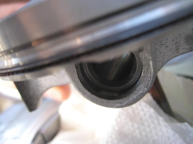
12.Install piston on crank (small exhaust valve recesses forward, and larger intake valve recesses aft) with piston pin and remaining piston pin clip. Once again, ensure clip ends are horizontal and facing aft.
13.While compressing piston rings with fingers, install piston in cylinder making sure not to catch wavy oil ring on cylinder. (I have installed piston into cylinder first, and piston onto crank first and both worked fine, but I find it easier to install the piston pin rings with the piston out of the cylinder, YMMV and I will get differing opinions on this one you just watch!).
14.Slowly lower cylinder onto case until dowel pins in case mate with cylinder.
15.Install dowel pins in fwd left side and aft right side of cylinder holes around long studs.
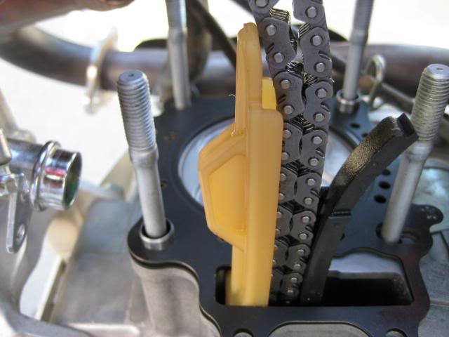
16.Install cam chain guide in square cutout on cylinder positioning cam chain guide tabs forward in cylinder cutout.
17.Install cylinder head gasket on cylinder and install cylinder head on cylinder.
18.Install 4 washers and 4 dome nuts on cylinder head studs (2 inside head and 2 outside head), and torque in a 3 step criss-cross pattern to 29 lb ft (348 lb in.). I use fingertight, 100, 250, and 348 lb in. steps.
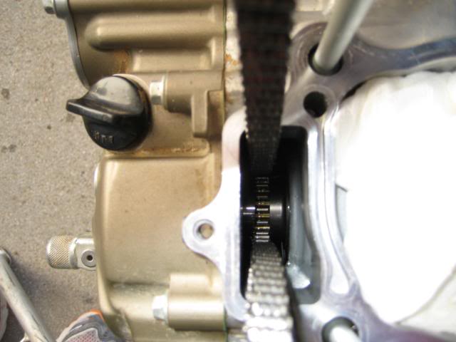
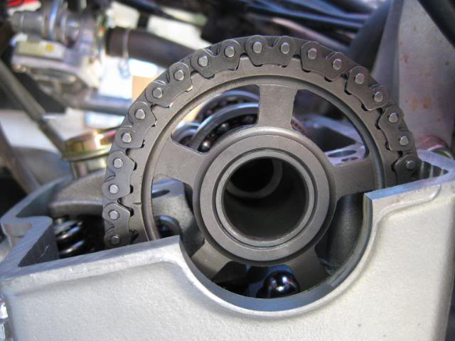
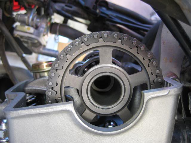
19.Install 2 small cylinder head bolts on lower left side of cylinder head and tighten with small bolt on lower left side of cylinder to 7 lb ft (84 lb in.).
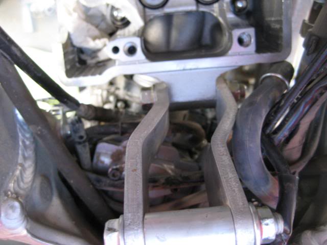
20.Install engine hanger plates on mount and cylinder head with bolts and nuts, and torque 40 lb ft (480 lb in.).
21.Ensure crank shaft is at TDC by aligning punch mark on crank with case arrow through access hole.
22.Install shims on top of exhaust valve spring openings using shims previously removed as a rough guide (mine were stamped 177).
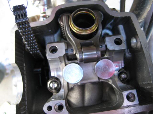
23.Install exhaust valve rocker arm (U-shaped) on cylinder head with rocker arm shaft ensuring cam cap bolt holes are aligned with holes in rocker arm shaft.
24.The rocker arm shaft will be free to move (if you didn't align it perfectly, don't sweat it) until the cam cap bolts are installed.
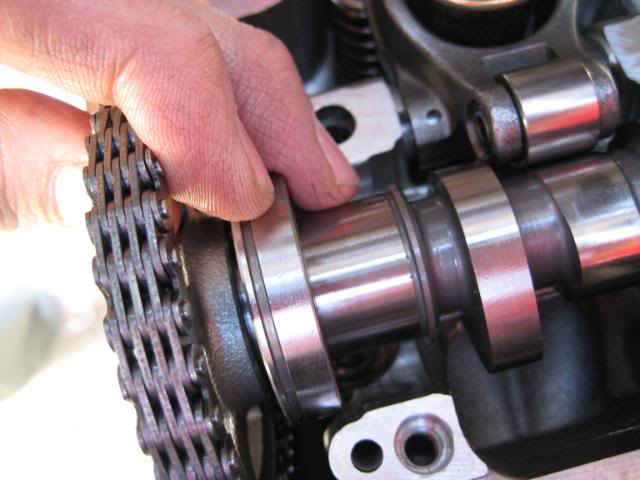
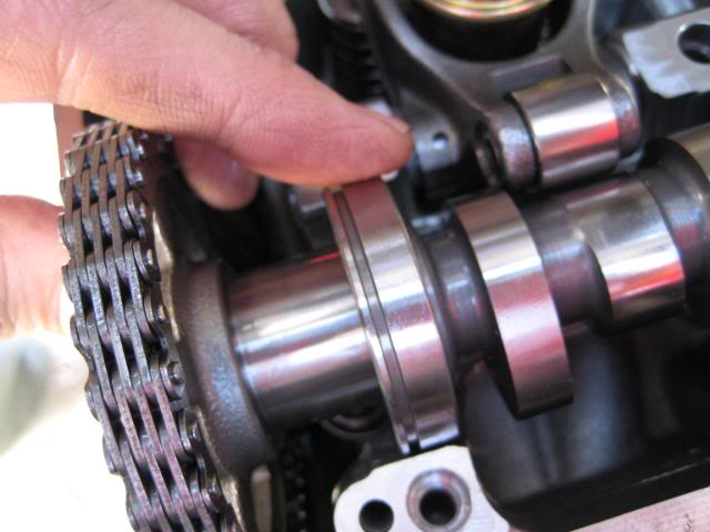
25.Verify cam chain is fully on lower sprocket (major area to watch and has caused many headaches) and position cam on head and under cam chain ensuring horizontal marks on cam are aligned with edge of head cover mounting surface. If cam is difficult to put on, cam chain is not fully on lower sprocket. Slide bearing on sprocket side of Cam onto seating area of head. It will slide a bit, so you need to lift the cam and slide it into position.
26.Install dowel pins in bottoms of camshaft holders (they probably stayed installed in the holders like mine did).
27.Install shims (start with 150/155 marked shims) in intake springs.
28.Install buckets over shims and valve springs 2 places.
29.Install set ring in groove of right camshaft holder (holder stamped with an R) and position on right side of cam shaft ensuring set ring is in recess on camshaft holder and in head recess.
30.Repeat for left side using holder stamped with an L.
31.Install longer bolts on forward side of camshaft holders and shorter bolts on aft side.
32.Snug, but do not tighten camshaft holder bolts at this time.
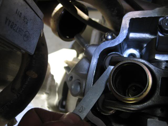
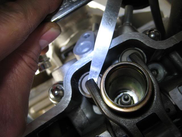
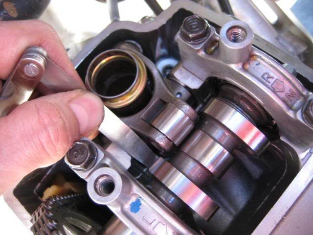
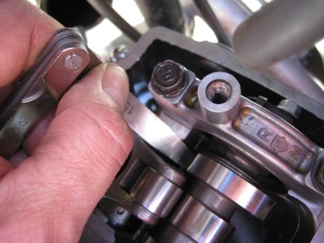
33.Check valve clearance. [IN: 0.005 ± 0.001 (0.12 ± 0.03 mm), EX: 0.011 ± 0.001 (0.28 ± 0.03)].
34.Adjust shims as necessary and torque camshaft holder bolts in a 3 step criss-cross pattern to 12 lb ft (144 lb in.). I use, fingertight , 50, 100, and 144 lb in.
35.Release CCT holder quickly to cause CCT to snap into position and tighten cam chain.
36.Install washer and bolt in CCT center hole where CCT holder was inserted using German torque.
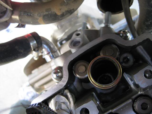
37.Install radiator hose metal piece on front of cylinder head with bolt using German torque.
38.Install smog tube on front of cylinder head with bolt using German torque.
39.Install cylinder head cover with bolts and torque to 7 lb ft (84 lb in.), do not overtighten.
40.With oil and spark plug out of engine, turn over engine by hand 50 times.
41.Install cover on crank opening snug, but do not over tighten.
42.Install oil in crankcase and install radiator fluid.
43.Install sparkplug snug, but not too tight. Factory recommendations will make it impossible to remove at a later time YMMV. If sparkplug is new, install fingertight plus ½ turn. If sparkplug is used, fingertight plus 1/8 turn.
44.Pop sparkplug cap onto sparkplug until you hear it click into postion, then push some more just to make sure it is fully seated (I usually hear 2 clicks, but 1 is acceptable).
45.Install oil breather hose on rear of cylinder head cover. Snap into plastic holder. There will also be a smaller curved hose attached to the plastic holder venting to atmosphere (an open end), so don’t look for a connection point.
46.Install small smog hose on lower right side of cylinder head. If you leave this off, there will be a carburetor leak and it will run poorly.
47.Lubricate carb boot lightly with petrolatum (Vaseline), and lower subframe until carb boot pops onto carb intake port. This is where an extra hand is useful.
48.Install lower part of subframe with bolts, torque to 36 lb ft (432 lb in.).
49.Torque upper subframe bolt and nut 22 lb ft (264 lb in.).
50.Install exhaust on front of head loosely but semi snug using new gasket and nuts.
51.Secure rear of exhaust using washer and bolt, torque to 20 lb ft (240 lb in.).
52.Torque front exhaust nuts 15 lb ft (180 lb in.).
53.Tighten screws securing carb boot clamps using German torque.
54.Install gas tank, petcock, seat, and previously removed plastic all using German torque.
Definitions:
Snug: Approximately 2 fingers on a wrench tight, but not enough to require a torque wrench.
German torque: A non-critical torque using nothing but a calibrated elbow and not tooooo tight.
Step torque: Torquing a bolt/nut using three values that increase until the final torque is reached. This is used with multiple bolts where all bolts shall be torqued evenly to keep even pressure applied.
Criss-cross pattern: Using an X pattern, alternate torque between opposite bolts. Normally applied to 4 or more bolts. When more than 4 bolts are used, the exact pattern is usually shown on a figure, like on a cars cylinder head bolts.
CW: Clockwise direction.
PARTS:
I used 13101-KRN-A10 piston
13011-KRN-A10 rings
Sheet A gasket set 06113-KRN-710 (includes head, cylinder, head cover, CCT gaskets all in one kit, service Honda has them)
13111-KRN-850 piston pin
13115-KM7-700 piston pin clips
1. Remove seat, tank, exhaust from front of cylinder head and at rear mount, smog line/bolt at front of cylinder, drain radiator and remove hose at front of cylinder, remove two lower subframe bolts, and loosen upper subframe bolt, loosen clamp holding carb at cylinder head, lift up subframe and separate carb with boot attached from cylinder head, remove cylinder head cover/bolts, wind up cam chain tentioner (CCT), remove cam holders/keepers/bolts, remove cam, remove cylinder head bolts and cylinder head, remove one lower cylinder bolt and cylinder, remove piston pin clip, piston pin, and piston. Whew, that was easy. Now the hard part.
2.Clean cylinder and piston using contact cleaner, and then hot soapy water.
3.Finish off inside of cylinder using ATF on a clean paper towel. Wipe until no more metal shows up on paper towel (leaves a trace of ATF on the cylinder hone marks).
4.Finish wipe using a clean paper towel until no more ATF residue shows up.
5.Wipe piston rings using a clean paper towel to remove excess oil.
6.Put piston pin clip in piston recess on CCT side first, before installing piston (limited access on this side, so do it before installing)(Piston pin clips shall be installed with open ends facing aft and horizontal.).
7.Install rings as shown:
a.Install wavy oil ring first in lower groove aligning cutout 90 degrees CW to the IN mark stamped on the piston. The oil ring must be installed first or it will hang up and not fully compress into the groove.
b.Install lower side rail below the oil ring (in the same groove) 180 degrees CW from the IN mark stamped on the piston which will be a further 90 degrees CW from the oil ring cutout.
c.Install the upper side rail above the oil ring (in the same groove) 270 degrees CW from the IN mark stamped on the piston which will be a further 90 degrees CW from the lower side rail cutout.
d.All three rings should be able to be compressed flush with the side of the piston with light finger pressure, if not, something is buggered up, probably the wavy oil ring.
e.Install the top ring in the upper groove ensuring the mark (RK in my case) is facing up and is 180 degrees CW from the IN mark stamped on the piston.
f.It is not critical that all these ring gaps be precisionally placed (I use ± ¼ inch), but just make sure none of the lower 3 ring gaps are aligned with each other. If they are aligned, oil can leak through from one ring to the next which is not good.
8.Put one drop of oil on piston pin and rub all over shinny surface.
9.Put one small drop of oil on finger and swipe on each side of piston skirt (at piston pin holes), but very little oil.
10.Install lower dowel pins into case holes at the fwd right side and aft right side.
11.Ensure mating surface is clean and install lower cylinder gasket (no sealant required).
12.Install piston on crank (small exhaust valve recesses forward, and larger intake valve recesses aft) with piston pin and remaining piston pin clip. Once again, ensure clip ends are horizontal and facing aft.
13.While compressing piston rings with fingers, install piston in cylinder making sure not to catch wavy oil ring on cylinder. (I have installed piston into cylinder first, and piston onto crank first and both worked fine, but I find it easier to install the piston pin rings with the piston out of the cylinder, YMMV and I will get differing opinions on this one you just watch!).
14.Slowly lower cylinder onto case until dowel pins in case mate with cylinder.
15.Install dowel pins in fwd left side and aft right side of cylinder holes around long studs.
16.Install cam chain guide in square cutout on cylinder positioning cam chain guide tabs forward in cylinder cutout.
17.Install cylinder head gasket on cylinder and install cylinder head on cylinder.
18.Install 4 washers and 4 dome nuts on cylinder head studs (2 inside head and 2 outside head), and torque in a 3 step criss-cross pattern to 29 lb ft (348 lb in.). I use fingertight, 100, 250, and 348 lb in. steps.
19.Install 2 small cylinder head bolts on lower left side of cylinder head and tighten with small bolt on lower left side of cylinder to 7 lb ft (84 lb in.).
20.Install engine hanger plates on mount and cylinder head with bolts and nuts, and torque 40 lb ft (480 lb in.).
21.Ensure crank shaft is at TDC by aligning punch mark on crank with case arrow through access hole.
22.Install shims on top of exhaust valve spring openings using shims previously removed as a rough guide (mine were stamped 177).
23.Install exhaust valve rocker arm (U-shaped) on cylinder head with rocker arm shaft ensuring cam cap bolt holes are aligned with holes in rocker arm shaft.
24.The rocker arm shaft will be free to move (if you didn't align it perfectly, don't sweat it) until the cam cap bolts are installed.
25.Verify cam chain is fully on lower sprocket (major area to watch and has caused many headaches) and position cam on head and under cam chain ensuring horizontal marks on cam are aligned with edge of head cover mounting surface. If cam is difficult to put on, cam chain is not fully on lower sprocket. Slide bearing on sprocket side of Cam onto seating area of head. It will slide a bit, so you need to lift the cam and slide it into position.
26.Install dowel pins in bottoms of camshaft holders (they probably stayed installed in the holders like mine did).
27.Install shims (start with 150/155 marked shims) in intake springs.
28.Install buckets over shims and valve springs 2 places.
29.Install set ring in groove of right camshaft holder (holder stamped with an R) and position on right side of cam shaft ensuring set ring is in recess on camshaft holder and in head recess.
30.Repeat for left side using holder stamped with an L.
31.Install longer bolts on forward side of camshaft holders and shorter bolts on aft side.
32.Snug, but do not tighten camshaft holder bolts at this time.
33.Check valve clearance. [IN: 0.005 ± 0.001 (0.12 ± 0.03 mm), EX: 0.011 ± 0.001 (0.28 ± 0.03)].
34.Adjust shims as necessary and torque camshaft holder bolts in a 3 step criss-cross pattern to 12 lb ft (144 lb in.). I use, fingertight , 50, 100, and 144 lb in.
35.Release CCT holder quickly to cause CCT to snap into position and tighten cam chain.
36.Install washer and bolt in CCT center hole where CCT holder was inserted using German torque.
37.Install radiator hose metal piece on front of cylinder head with bolt using German torque.
38.Install smog tube on front of cylinder head with bolt using German torque.
39.Install cylinder head cover with bolts and torque to 7 lb ft (84 lb in.), do not overtighten.
40.With oil and spark plug out of engine, turn over engine by hand 50 times.
41.Install cover on crank opening snug, but do not over tighten.
42.Install oil in crankcase and install radiator fluid.
43.Install sparkplug snug, but not too tight. Factory recommendations will make it impossible to remove at a later time YMMV. If sparkplug is new, install fingertight plus ½ turn. If sparkplug is used, fingertight plus 1/8 turn.
44.Pop sparkplug cap onto sparkplug until you hear it click into postion, then push some more just to make sure it is fully seated (I usually hear 2 clicks, but 1 is acceptable).
45.Install oil breather hose on rear of cylinder head cover. Snap into plastic holder. There will also be a smaller curved hose attached to the plastic holder venting to atmosphere (an open end), so don’t look for a connection point.
46.Install small smog hose on lower right side of cylinder head. If you leave this off, there will be a carburetor leak and it will run poorly.
47.Lubricate carb boot lightly with petrolatum (Vaseline), and lower subframe until carb boot pops onto carb intake port. This is where an extra hand is useful.
48.Install lower part of subframe with bolts, torque to 36 lb ft (432 lb in.).
49.Torque upper subframe bolt and nut 22 lb ft (264 lb in.).
50.Install exhaust on front of head loosely but semi snug using new gasket and nuts.
51.Secure rear of exhaust using washer and bolt, torque to 20 lb ft (240 lb in.).
52.Torque front exhaust nuts 15 lb ft (180 lb in.).
53.Tighten screws securing carb boot clamps using German torque.
54.Install gas tank, petcock, seat, and previously removed plastic all using German torque.
Definitions:
Snug: Approximately 2 fingers on a wrench tight, but not enough to require a torque wrench.
German torque: A non-critical torque using nothing but a calibrated elbow and not tooooo tight.
Step torque: Torquing a bolt/nut using three values that increase until the final torque is reached. This is used with multiple bolts where all bolts shall be torqued evenly to keep even pressure applied.
Criss-cross pattern: Using an X pattern, alternate torque between opposite bolts. Normally applied to 4 or more bolts. When more than 4 bolts are used, the exact pattern is usually shown on a figure, like on a cars cylinder head bolts.
CW: Clockwise direction.
PARTS:
I used 13101-KRN-A10 piston
13011-KRN-A10 rings
Sheet A gasket set 06113-KRN-710 (includes head, cylinder, head cover, CCT gaskets all in one kit, service Honda has them)
13111-KRN-850 piston pin
13115-KM7-700 piston pin clips

 My bad, natural instinct. Alright keep them coming, will be very informative for the forum.