I have been having some electrical problems with my CR 250, as you guys know the manual says you need a peak voltage adapter. They are pretty expensive to buy so I made one and wanted to share with you guys how to build it. Everything including the box and test leads cost me about $9.00 at the electronics store. So here are the schematics.
D1 - is a Diode and the line after the triangle shows which way to mount it, there is a line on the actual Diode itself. (this only lets electricity pass through one way.
C1 - is just a Capacitor to store the volts so you can read them
R1 - is just a small resistor.
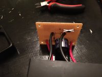
Anyways here are some pictures of the one I made. It works great (unfortunately my bike doesn't !!)
The white X is a mess up that I didn't take out so don't pay attention to that.


D1 - is a Diode and the line after the triangle shows which way to mount it, there is a line on the actual Diode itself. (this only lets electricity pass through one way.
C1 - is just a Capacitor to store the volts so you can read them
R1 - is just a small resistor.
Anyways here are some pictures of the one I made. It works great (unfortunately my bike doesn't !!)
The white X is a mess up that I didn't take out so don't pay attention to that.